Before beginning a new modeling project, especially one that is related to thermal comfort, it is essential to clearly define the specific issues and expectation of the client. This provides the basis for the process to identify satisfying solutions. For our project in Munich, Germany the client asked us how we can help to improve the thermal comfort and the air quality of a cafeteria and two office spaces, located on the top floor of a seven-story building. The rooms are ventilated and conditioned by a dedicated outdoor air system in combination with a radiant cooling system.
The initiative of the client was triggered by the result of a building occupant survey, which clearly identified that specific rooms are too hot and that the air quality of the cafeteria is poor. In engineering terms, it implies that one, or most likely a combination of the following factors is out of the target range:
- Air temperature
- Radiant temperature
- Humidity
- Ventilation rate
Step 1 – On-site data acquisition and inspection of the as-built drawings
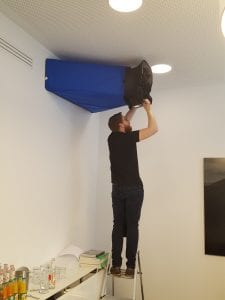
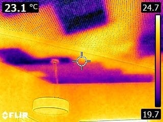
In order to improve thermal comfort and air quality, an on-site inspection was carried out. The actual supply airflow rates were measured (see Figure 1) and compared with the designed target supply airflow rates. In addition, tomographic images were taken to check the function of the radiant cooling elements (see Figure 2).
The results showed that only one room met the designed airflow rates. The other two rooms were 17 % and 49 % below the design values. With the help of the thermographic images, it was possible to confirm that the radiant ceilings operate as expected. However, the active area was significantly smaller than specified in the as built drawings.
Step 2 – Creation of the thermal-dynamic model
A thermal-dynamic model was created to ensure that the impact of the solar heat gain and occupant behavior over the course of a whole year is considered for the sizing of the additional cooling equipment. The model was based on the as-built drawings and the recorded data during the onsite visit including building physics, technical system, control data as well as occupant behavior. IESVE was selected as the simulation environment/software. With IESVE, it was possible to efficiently create the 3D building geometry and to effectively model the complex controls of the cooling and ventilation equipment.
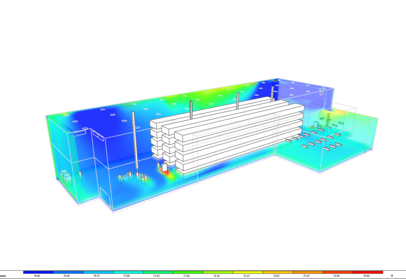
The graph on the left represents the indoor air temperature of the selected spaces before the implementation of optimization measures. The upper three visualizations are colored representations of the room air temperature for three different times on a summer day in August. The scatter plot reveals the room air temperature as a function of the outside air temperature over the course of a year and identifies the hours when the room temperature goes beyond the targeted range (unmet hours of thermal comfort).
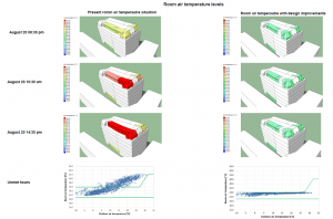
The simulation results of the initial situation demonstrate that the installed cooling equipment is significantly undersized. Furthermore, the installed shading device does not effectively prevent the penetration of solar radiation. Overall, this leads to a significant overrun of the indoor air temperatures as well as extreme temperatures at the fenestration surfaces – above 140F / 60°C. In summary, the simulation results confirm the occupant’s complaints about thermal comfort issues.
Step 3 – Verification of measures in the thermal-dynamic model
The model was used to analyze a range of potential solutions and to size the selected cooling equipment. The final selection of measures included:
- Installation of an optimized external shading device
- Increase of cooling capacity through fan coil units
- Increase of airflow rates
These measures allow the room air temperatures to be maintained within an acceptable comfort range (see Figure 3). The green color in the visualization of the room air temperature in the 3D model and the scatter plot with room temperatures have supported the decision-making process and helped to convince the client of the proposed measures.
If you are interested in our modeling services, please view the following link for more information find out more here.
